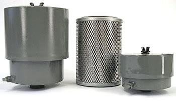
Smoke Eliminator
Ultra-fine Element Stops the Smallest Dirt Particles
Two-stage element helps guard against air pollution and conserves lube oil.Applications
Falls Filtration Technologies vacuum pump exhaust smoke eliminators are designed to eliminate the finely divided oil smoke found in gases discharged from rotary types as well as droplets from reciprocating-type vacuum pumps. These lightweight units can be mounted directly on the pump, or on a discharge pipe common to several pumps. Yet, they are versatile enough to allow remote mounting.The units may be installed indoors or outdoors. And the in-line models allow clean exhaust from the eliminator to be piped to a remote location or back into process.
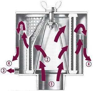
- 1. Oil-laden air enter Smoke Eliminator.
- 2. The 2-stage element cleans the exhaust air.
- 3. Collected air drains from Eliminator through drain connection to independent reservoir or back to vacuum pump, if system permits.
- 4. Clean exhaust air is discharged.
Smoke Eliminator Process Diagram
Enjoy These Benefits
Lube oil collected from the exhaust can be drained to an independent oil reservoir or returned to the pump if system permits ... Air from thee pump is clean and free of oil smoke. Clean exhaust helps guard against pollution and adds to in-plant safety.
Performance
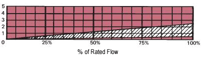
Eliminator will remove over 99.95% of all oil smoke from discharge gas. Back pressure imposed on pump by smoke eliminator will range from 1/2 to 2 1/2 psi maximum at rated flow, depending upon amount of oil present in discharge gas. Range of back pressures to be expected at various percentages of maximum flow rates is shown in graph at right. Back pressure is established by degree of saturation of eliminator element which, in turn, depends on amount of oil smoke discharge by pump. This will vary with make, model, type and condition of pump... In-line models are suitable for systems with up to 10-psi operating pressure.
Back Pressure Pounds per Square Inch
Because of the vertical filter element and oil control ring, Falls Filtration oil bath filters do not hold oil suspended in the element at high air flows. Oil automatically returns to sump for recirculation. The oil washing action takes place at all speeds; from idle to full throttle.
Construction
Eliminators are constructed of welded steel and are finished with gray, baked, oil and weather-resistant enamel. A full hood provides protection against the weather. The two-stage element is made of inert material. End seals are oil-resistant plastics and prevent leakage around the end of the element ... Replacement element kits are available, although element service life is extensive ... Units are easily disassembled and re-assembled without special tools ... Connection sizes are available for a wide range of applications.Connection Types & Sizes Available
|
Installation, Servicing, and Trouble-Shooting Instructions
Accumulated oil must periodically be drained from the eliminator through the drain plug provided. Time interval will vary with each installation, but frequent inspection will easily establish a proper service schedule. If manual draining is required more frequently than appears to be practical, a commercial-type automatic trap can be connected to the drain, or the drain can be piped to an external sump. Where it is possible to connect the drain to a low pressure point in the pump (to continuously return the collected oil), provisions should be made to limit the amount of air returned with the oil.
Eliminator element should be replaced if (1) a loss of performance efficiency is observed, or (2) back pressure has increased through the element, resulting in lengthy pump downtime or difficulty in maintaining required vacuum in system. When reassembling the eliminator following element replacement, be sure to tighten cover retainer nuts to prevent bypass of oil smoke around ends of the element.
The following corrective action is recommended if, a) discharge smoke is observed emerging from under the cover of open-type eliminator modes. b) discharge smoke passes from the discharge outlet of in-line models. 1. Inspect element ... if a rupture or crack is evident, the element should be replace. (See Table on Page 4.) 2. If element appears relatively clean inside and out, and no ruptures or cracks are evident, inspect the end seals ... if they appear to be cracked or feel exceptionally hard, add a gasket of a soft commercial gasket material to each end. When reinstalling element, be sure it seals completely at each end to prevent smoke bypass.
On in-line models, also be sure to tighten top cover plate against the gasket.
How to Order & Sizing
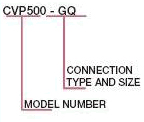
First, select a model number based on CFM capacity required (up to maximum shown in Table here). Then add proper code letters from table below to indicate desired connection size and type; example – Model VP20 with 2” female pipe thread is VP20FL... To order replacement element, select from Table on Page 4 and be sure to include suffix; example – Replacement element part number for a Model V100 is 200256-8.Select proper size by matching airflow capacity of the eliminator (see Table here) to the CFM capacity of the vacuum pump, or the sum of the capacities where more than one pump are manifolded into one discharge line. If imposed back pressure on pump is critical, derate to per cent of rated flow (shown in graph on Page 2) for maximum back pressure allowable.
Smoke Eliminator:
Request a Smoke Eliminator Brochure in PDF Format
Falls Filtration Technologies reserves the right to change any model or specification at any time without notice.